

Objective
For the past two years, I have been trying to understand how the data retrieved from a Redox probe works and how it is interpreted. I have a salt pool and controlling the Redox seems like a good way to monitor water disinfection.
The page Redox (ORP) or Ph home automation control from a pool to Jeedom described my installation and the management of the Redox was missing because when I created my installation, I had not been able to understand it despite the many forum and tutorial readings. Each using its own formula. Thanks also to the support of Phidgets who directed me to the right method.
Description of the installation
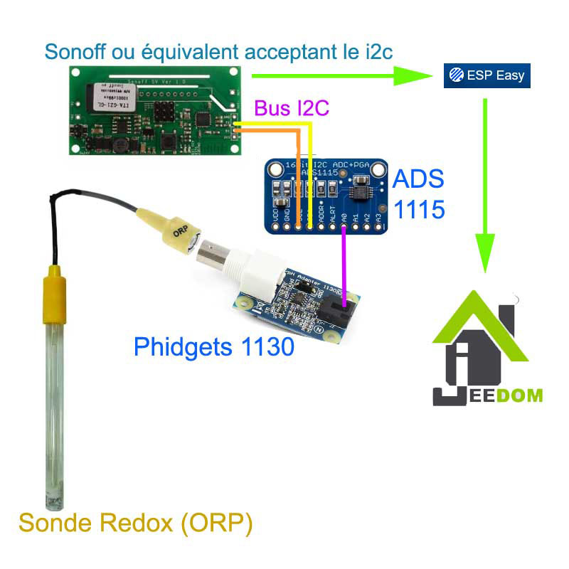
A pattern that is always better than a long speech, here is the installation
Difficulties encountered
It was difficult to go through the steps to ‘translate’ the probe’s info and then that of the 1130 which entered the analogue input of the ADS1115 and then decode it to send it to Esp Essay and Jeedom. The aim was to find a value in mV.
Information retrieved from the Redox probe
The probe measures the redox potential defined between -2000mV and +2000mV. If Redox is greater than 0, the water is oxidizing. The higher this value, the more chlorine there is in the water.
This article describes very well the principle of ORP probes: http://www.piscine-clic.com/news/2014/02/potentiel-redox-kezako/
The problem is that this probe comes out a very weak current, we can not read it precisely in this way, we must add an amplifier that will at the same time raise the voltage to read it.
The Phidgets 1130
Full documentation of this adapter can be found here: http://www.phidgets.com/docs/1130_User_Guide
What will be useful for us is the decoding formula based on:
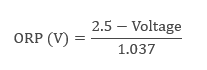
Reading this formula, we realize that a simple rule of proportionality between the output value and a coefficient to be defined will not work. The calibration points proposed by ESP Easy will therefore not be reliable since nothing is linear.
The difficulty is figuring out what value takes Voltage and the link between this Voltage and the value retrieved on the analog input A0 of ADS1115.
Gain timing on ADS 1115
The configuration of the analog input of the ADS1115 is simple, the only difficulty is the timing of the gain. The 1115 is equipped with a programmable gain amplifier. It is therefore he who must be put in order otherwise nothing will work properly.
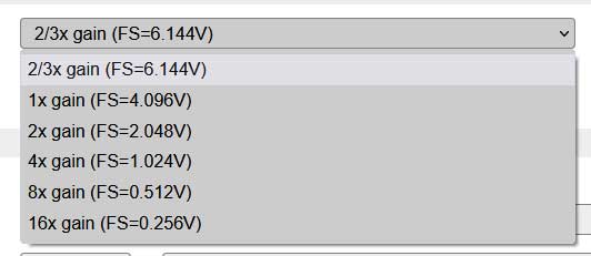
To know which value to choose, I tested the ADS1115 on the two specific operating values, 0v and Vcc (close to 5v) on all gains, and I finally chose the gain that allows me to test a value greater than 4.096v, so you have to use this gain:
2/3x gain (FS=6.1444V)
- For A0=GND=0v, I obtained a result of -19
- For A2=Vcc=5.02v, I obtained a result of 26697
What suits me, all measurements will be made between these two values.
With this configuration, the measurement step is 6.144v/32767=0.000187506v
- 6.144v corresponds to the FS value chosen in the gain
- 32767 is the number of steps, since ADS1115 has a 16-bit resolution (ranging from -32768 to 32767). The ADS1015 is on 12 bits so -2048 to 2047.
Note: : Some documentation contradicts each other, sometimes we use FS/32767 sometimes Vcc/32767. For my part FS gives empirically a good correspondence.
Calculation of the "Voltage" of 1130
The first step in our calculation is to find the value of Voltage to be injected into the formula provided in the documentation of 1130.
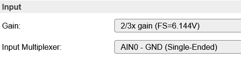
Thus, there is necessarily a correspondence between the measured value between A0 (Value measured between AIN0 and mass) and the value of Voltage we're looking for.
In Esp Easy, we will choose this configuration:

Calibration method
I used a buffer dose at 468mV to perform my tests.
Step 1: Dip the probe into the buffer solution 468mV
Step 2: To measure by voltmeter the value of the voltage between Data and GND of the 3 output wires of the 1130, I find: 2.01v
Step 3: Raise on Esp Easy the value given on A0, I find 10636
I know from other value tests that I need to add an offset (or calibration value), I will use the following formula:
Voltage = (A0 + MonOffset) * ValueDuPas
- as explained above the value of the step is ValueDuPas=0.000187506v (or use 6.144/32767)
In my example A0=10636, my offset, I set it to 99, so we have the following calculation:
Voltage = (10636 + 99) * 0.000187506 = 2.01287393, the voltmeter gave us 2.01v
So we have at this point the link between the value given by the ADS1115 and the output voltage of the 1130.
Calculation of the Redox value
As explained in the documentation of 1130, we will use the following formula:
In my calculation, I will multiply by 1000 to have the result in mV.
ORP(mV) = 1000*(2.5-Voltage)/1.037
If I take the values with the buffer solution 468mV, I find:
ORP(mV) = 1000 * (2.5 – 2.01287393)/1.037 = 469.74mV
I will consider that the value is good!!
ESP Easy configuration
In ESP Easy, it was necessary to find a way to enter a complex formula in few characters, the formula field is limited, here is the configuration I used:

Summary and 3 tests with 3 buffer solutions
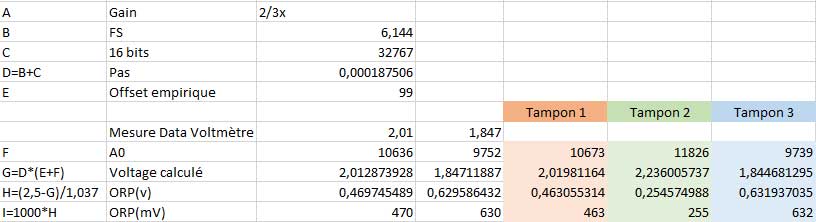
Once the formulas were put in place, I re-tested my device with 3 buffer solutions (see table).
Buffer solution 1:
- Solution is stamped 468mV
- This type of solution sells commercially and is quite simple to find.
- The orange column of the table gives 463mV as a result, which is satisfactory.
Buffer solution 2:
- It is an ordered bag among Chinese friends, stamped 256mV
- The green column of the table gives 255mV as a result, which is satisfactory.
Buffer solution 3:
- Solution is "old", from last year, it is stamped 650mV but its value has probably varied over time.
- The blue column of the table gives 632mV as a result, which is satisfactory.
 English
  French
  Spanish
  Chinese
  German